03Case study
Parametric blade tooling: closing the loop between optimiser and manufacture
A parametric tool taking optimiser output directly to manufacturable geometry, and measured parts back to parameters.
- Role
- Self-initiated · design, build, deployment
- Dates
- 2020
- Status
- Delivered · used in production design work
- Disciplines
- Computational design · Parametric CAD · Toolmaking
- Processes
- Grasshopper · Rhino · STEP · 3D scanning
Problem
The blade design pipeline ran through two specialists. An acoustics researcher had built an optimiser that generated candidate blade definitions quickly, an approximation rather than a full simulation, producing parameters as a spreadsheet. A second engineer then ran full ANSYS simulation to establish whether a candidate actually performed.
Between them sat a manual step. Before anything could be simulated, the ANSYS engineer had to build the blade by hand in Fusion from the spreadsheet, constructing every profile. A PhD simulation specialist was spending his time on CAD data entry, and the number of candidates that could be evaluated was set by how fast someone could redraw them rather than by how fast the optimiser could produce them.
The bottleneck belonged to neither specialist. Each was optimising his own end; the handoff between them was nobody’s job.
I built the tool during the first New Zealand lockdown. Everyone was working from home, and it was the useful thing I could do from a desk.
Constraints
- Output had to be solid, manufacturable geometry rather than a mesh or an approximation, usable by both ANSYS and outside suppliers without conversion
- Had to run from optimiser output with no human redrawing in the loop
- Needed to work in reverse: a scanned physical blade back to the parameters that describe it
- Built solo, remotely, alongside other work
Decisions
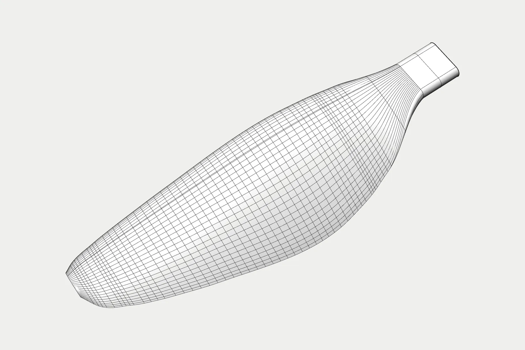
A parametric definition in Grasshopper, driven by CSV. Feed it the optimiser’s output and it produces a STEP file ready to simulate or send to a manufacturer.
The aerofoil and the root interface are separate parameters, so the same definition generates fixed blades and blades that mount into folding hubs. A candidate can go to either without being redrawn, which matters because the hub choice is usually made after the aerodynamics are settled.
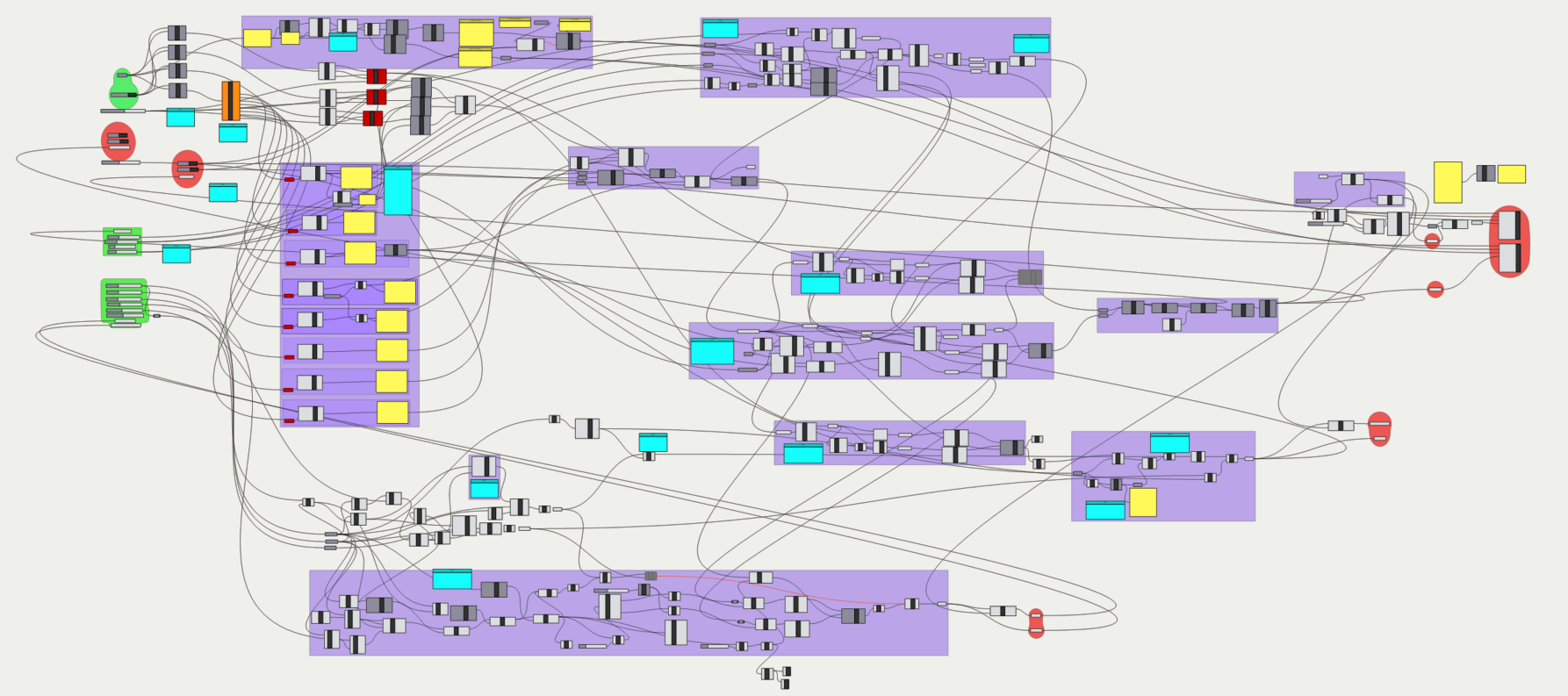
STEP rather than a mesh format because it is the one representation both the simulation side and the supply side accept as-is. A mesh would have needed rework at both ends, which reintroduces exactly the manual step the tool existed to remove.
The inverse path, scan to CSV, matters more than it sounds. It closes the loop between as-designed and as-manufactured, so a physical blade can be measured and expressed in the same parameters the optimiser works in. Without it you can generate designs but never verify what actually came back from the supplier.
Outcome
Building a blade went from over an hour of manual modelling to seconds. How many candidates reached full simulation stopped being a function of CAD time.
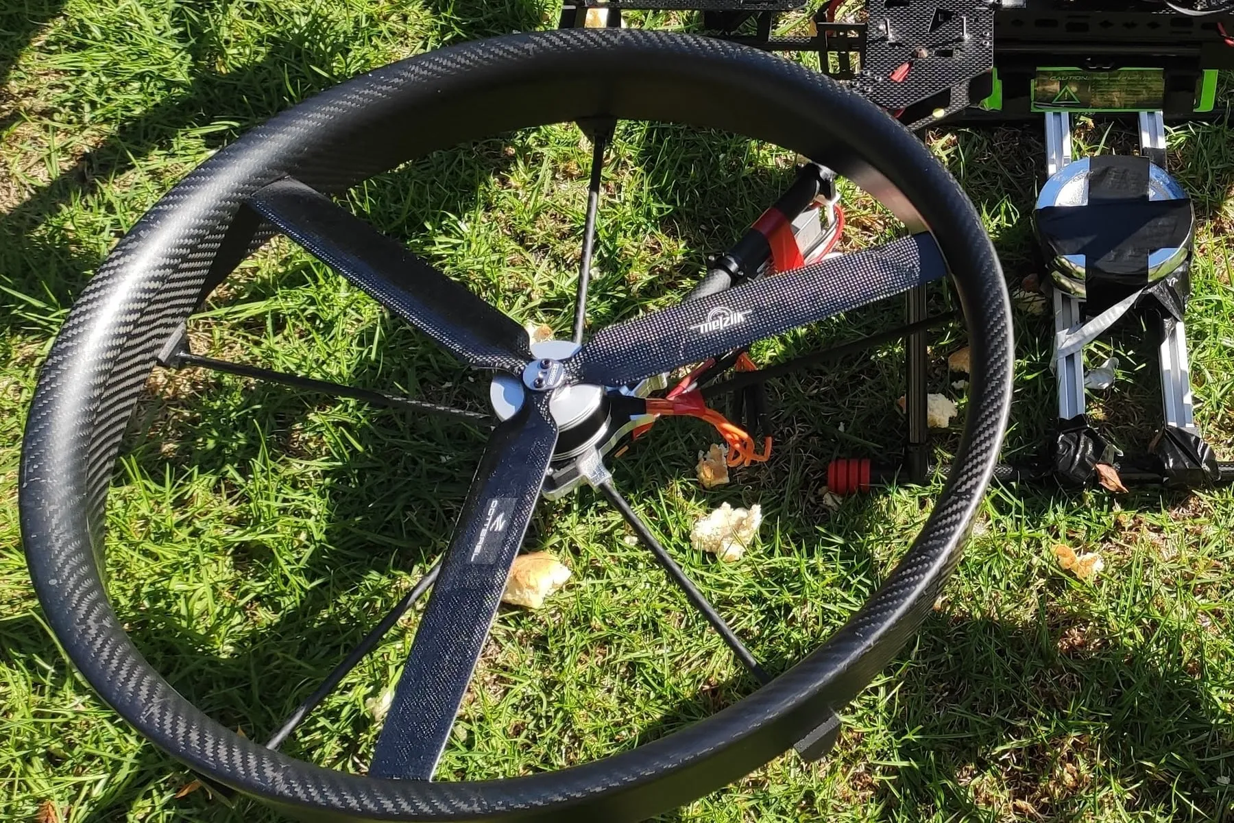
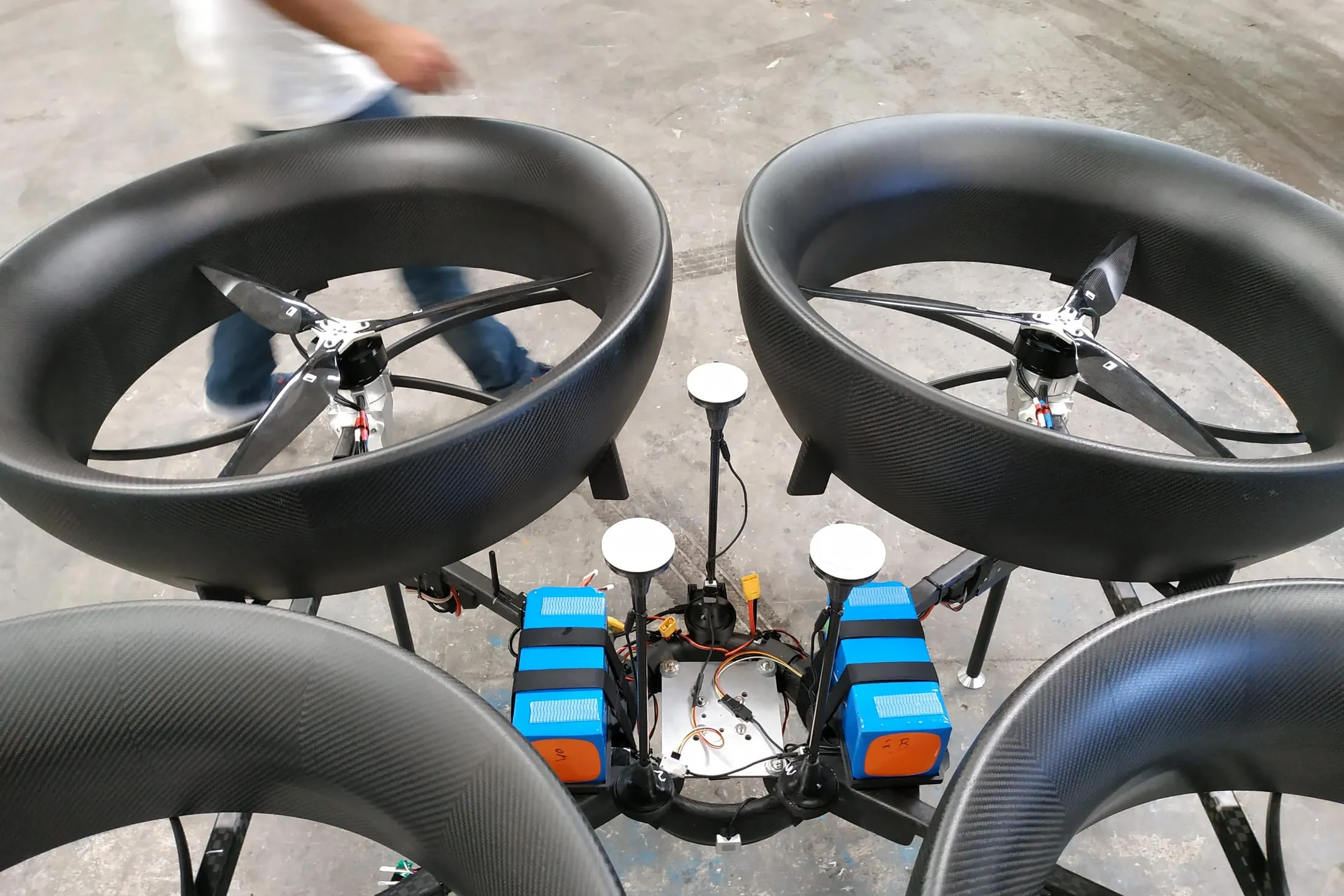
The tool produced blades used in shroud development and for an external customer, and returned a PhD simulation engineer to simulation work.
More work
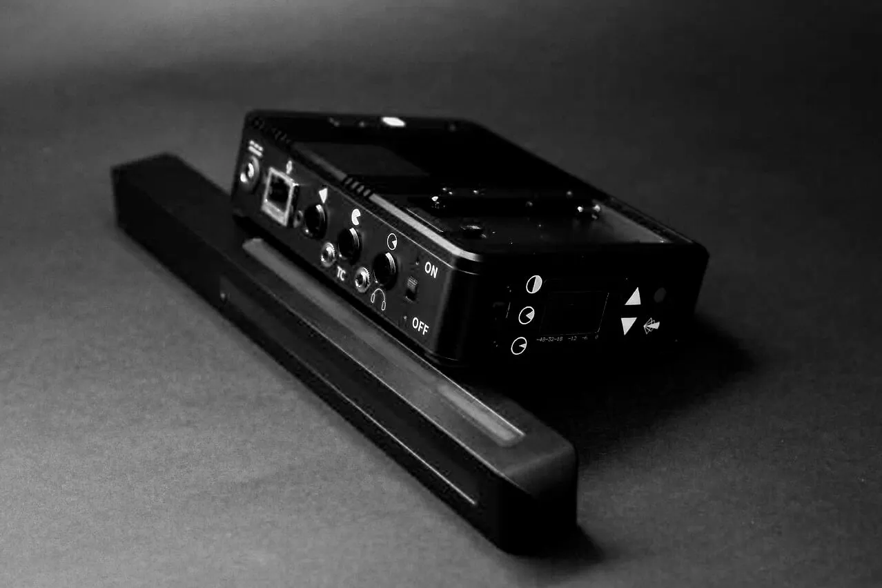 02Aerial Audio: building the aircraft the technology neededFive years designing and building the airframes, RF links and ground stations a microphone array needed in order to be tested at all.Read case study →2015–2019Superseded · became Konos
Contact
Auckland, New Zealand · NZ citizen with Australian work rights